
Science · JCE / Electricity and magnetism
StructuredPast exam questionForm 3 · JCE
The first diagram shows a simple electrical circuit: two cells, a switch, a bulb, and two meters. The scale diagram shows the reading on the ammeter when the switch is closed.
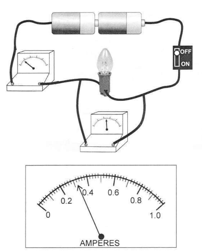
- aDescribe the circuit diagram that represents the circuit (draw it on paper). [3]
- bRecord the ammeter reading, I. [1]
- cCalculate the resistance of the bulb, using IR = 3, where I is the ammeter reading and R is the resistance. [2]
You'll mark your own answer against the marking guide when you hand it in.
Source: BEC JCE Science 2016, Paper 2, Question 10
Report a problem
More like this
- Three 2 Ω resistors are connected in series. What is the total resistance?
- A current of 2 A flows through a 6 Ω resistor. What is the voltage across it?
- A torch has two 1.5 V cells in series and a bulb with a resistance of 6 Ω.
- The diagram below shows a circuit used to investigate one of the factors affecting resistance of a wire. Three wires S, T and U of the same material,…
- The diagram below shows a set up used to magnetise a piece of iron nail.
- The diagram below shows an electric circuit with two identical bulbs and an electric component labelled P.
- The table below shows circuit symbols for some circuit components. Two have been named: variable resistor and connecting wires.
- The diagram below shows a circuit with a 12 V supply, a 4 Ω resistor, a 2 Ω resistor and an ammeter, all in series.