
Science · JCE / Electricity and magnetism
StructuredPast exam questionForm 3 · JCE
A set-up was used to investigate the relationship between the length of a wire and its resistance. The voltmeter measured the potential difference across different lengths of the wire.
Length (cm) / Voltage (V) / Resistance (Ω): 0 / 0 / 0; 15.0 / 2.0 / 2; 30.0 / 4.0 / 4; 45.0 / 6.0 / ?; 60.0 / 8.0 / 8; 90.0 / 12.0 / 12. (Plot the graph on paper.)
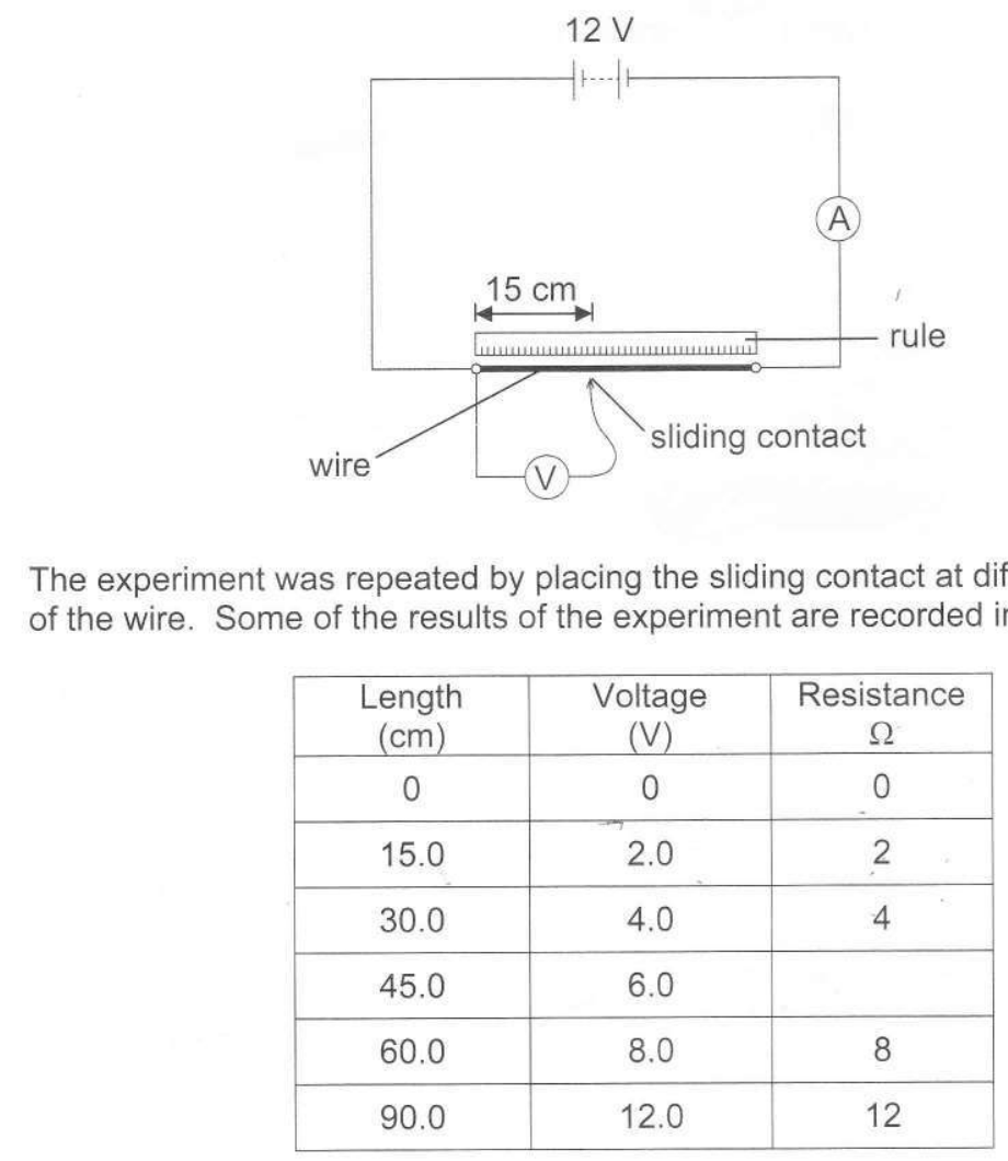
- aThe current was 1.0 A. Calculate the resistance at the 45.0 cm mark, using R = V ÷ I. [1]
- bUsing your graph, find the resistance when the sliding contact is at the 75.0 cm mark. Show your working. [2]
- cWhat conclusion can be drawn from the investigation? [1]
- dState one factor which affects the resistance of a wire apart from its length. [1]
- eWhich instrument is used to measure current? [1]
You'll mark your own answer against the marking guide when you hand it in.
Source: BEC JCE Science 2014, Paper 2, Question 11
Report a problem
More like this
- Three 2 Ω resistors are connected in series. What is the total resistance?
- A current of 2 A flows through a 6 Ω resistor. What is the voltage across it?
- A torch has two 1.5 V cells in series and a bulb with a resistance of 6 Ω.
- The diagram below shows a circuit used to investigate one of the factors affecting resistance of a wire. Three wires S, T and U of the same material,…
- The diagram below shows a set up used to magnetise a piece of iron nail.
- The diagram below shows an electric circuit with two identical bulbs and an electric component labelled P.
- The table below shows circuit symbols for some circuit components. Two have been named: variable resistor and connecting wires.
- The diagram below shows a circuit with a 12 V supply, a 4 Ω resistor, a 2 Ω resistor and an ammeter, all in series.